Weight: 0.17 kg
- USB TO UART/I2C/SPI/JTAG x1
- USB type A to type B cable ~1.2m x1
- 12PIN cable ~20cm x1
- 6PIN cable ~20cm (2PCS) x1
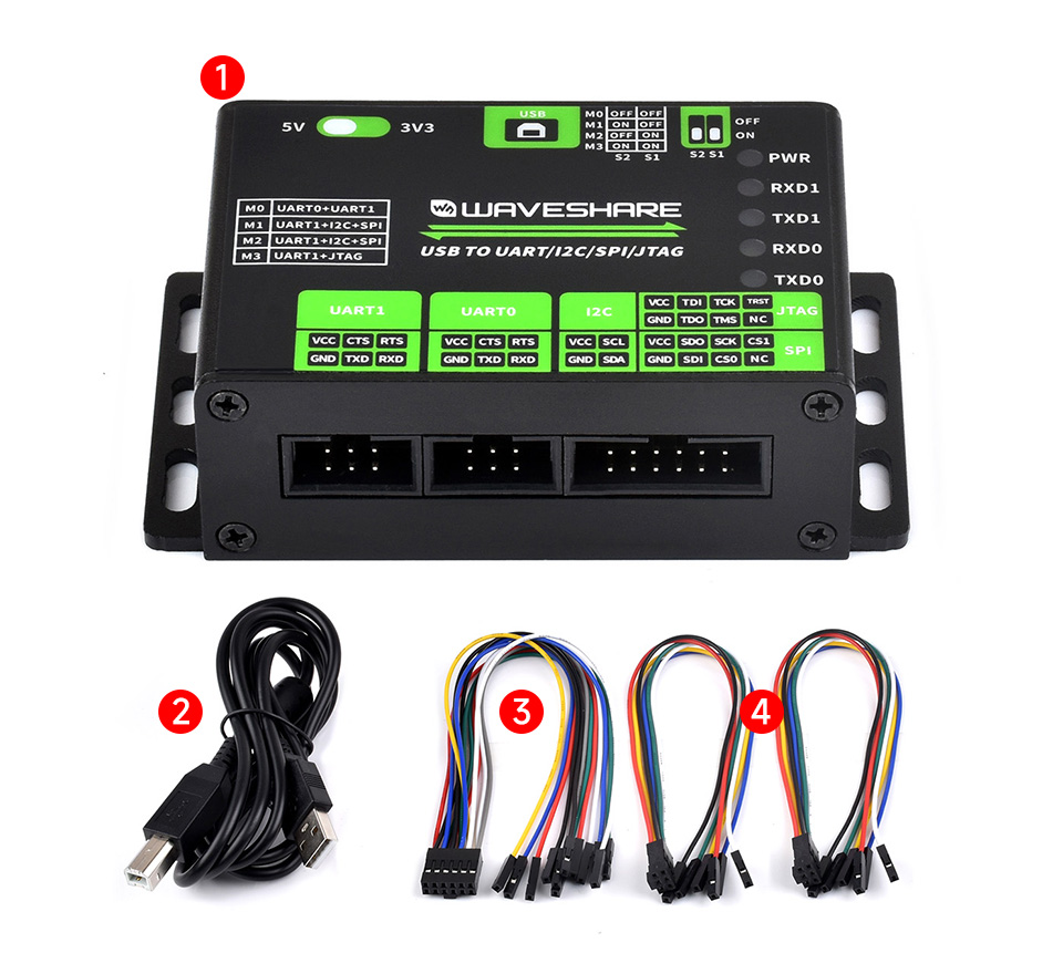
USB To UART/I2C/SPI/JTAG Converter, Supports Multiple Interfaces, Compatible With 3.3V And 5V, Multiple Protection Circuits, Multiple Systems Support, Aluminum Alloy Case, Wall-Mount & Rail-Mount Support
USB TO UART/I2C/SPI/JTAG
Supports Multiple Interfaces | Compatible With 3.3V And 5V
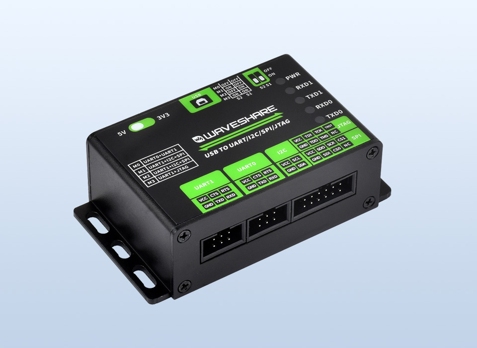
Features At A Glance
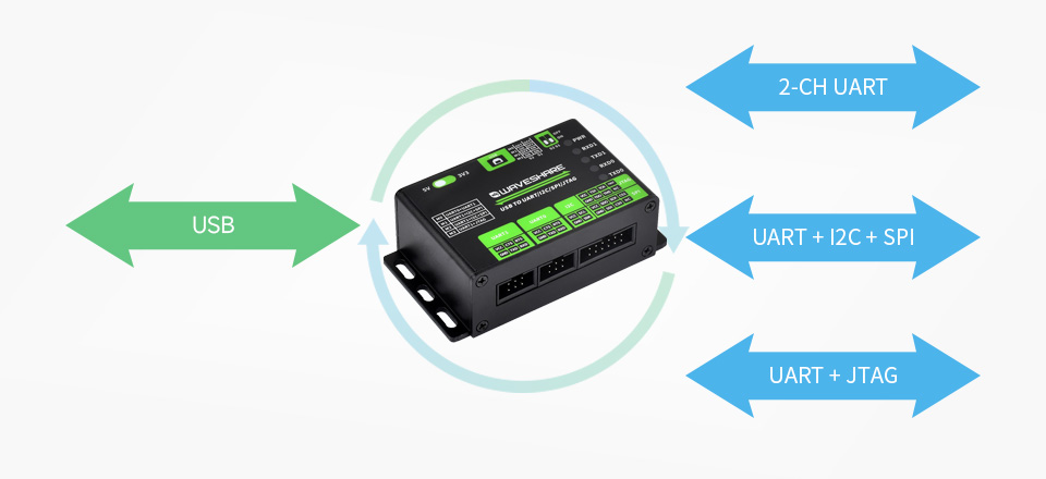
- Supports USB to 2-ch UART, or USB to 1-ch UART + 1-ch I2C + 1-ch SPI, or USB to 1-ch UART + 1-ch JTAG
- Supports 2-ch high-speed UART interfaces, up to 9Mbps baud rate, with CTS and RTS hardware automatic flow control
- Supports 1-ch I2C interface, for easy operating EEPROM through the host computer or programming I2C devices such as OLED and sensor
- Supports 1-ch SPI interface, with 2x chip select signal pins, capable of controlling 2-ch SPI slave devices at different times
- Supports 1-ch JTAG interface, can be used with OpenOCD for debugging and testing (Due to the limited testing of chips and software functions, users need to evaluate and test this function on their own)
- Onboard 3.3V and 5V level conversion circuit for switching the operating level of the communication interface, better compatibility
- Onboard resettable fuse and ESD protection circuit, provides over-current/over-voltage proof, safe and stable communication
- Aluminium alloy case with oxidation dull-polish surface, CNC process opening, solid and durable, well-crafted
- High-quality USB-B and DC connectors, smooth plug & pull, durable and reliable, with anti-reverse protection
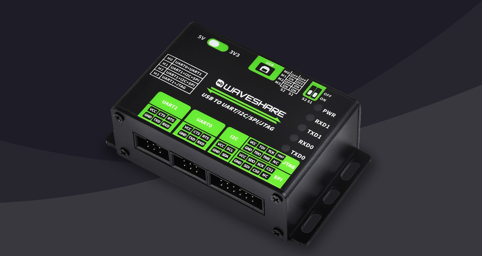
Specifications
| HOST INTERFACE |
USB |
| POWER SUPPLY |
USB port, 5V |
| OPERATING LEVEL |
3.3V/5V (select via onboard switch) |
| USB |
Connector |
USB-B |
| Interface protection |
Resettable fuse, ESD protection |
| UART |
Channel |
2 (the red DIP switch needs to be set to M0 mode) |
| Connector |
6PIN IDC connector |
| Baud rate |
1200bps~9 Mbps |
| Hardware flow control |
CTS and RTS |
| I2C |
Channel |
1 (the red DIP switch needs to be set to M1/M2 mode) |
| Connector |
12PIN IDC connector (the first 4 pins are I2C) |
| SPI |
Channel |
1 (the red DIP switch needs to be set to M1/M2 mode) |
| Connector |
12PIN IDC connector (the last 8 pins are SPI) |
| JTAG |
Channel |
1 (the red DIP switch needs to be set to M3 mode) |
| Connector |
12PIN IDC connector (the last 8 pins are JTAG) |
| DIMENSIONS |
86.0×48.0×27.6mm |
Primary Function
Easy To Control And Debug Various Interface Devices Via PC, Supports USB To 2-Ch UART, Or USB To 1-Ch UART + 1-Ch I2C + 1-Ch SPI, Or USB To 1-Ch UART + 1-Ch JTAG
Multi System Support
Supports Win7/8/8.1/10/11, Linux, Etc.
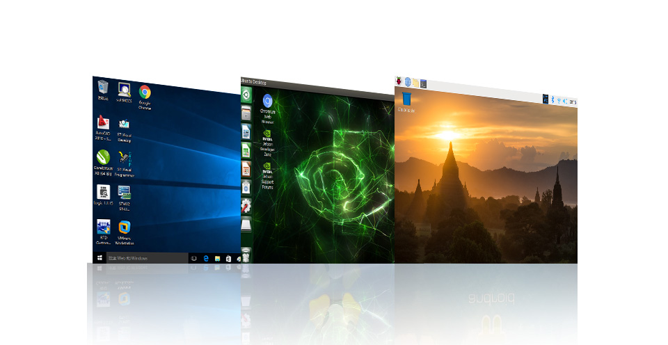
Application Environments
Suitable For College Students, Technical Engineers, Electronic Enthusiasts, Or DIY Makers For Learning And Debugging
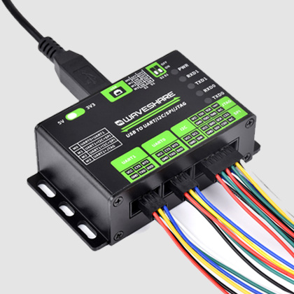
Supports Various Interfaces
Supports multiple communication debugging interfaces, most of which can be used at the same time
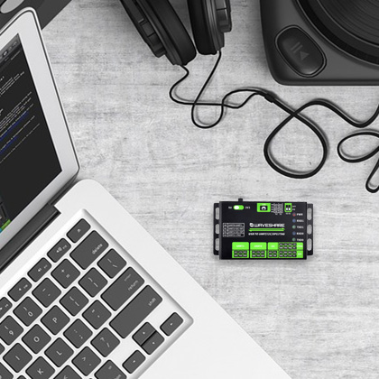
Small and compact, easy to install
Flexible installation, suitable for various devices
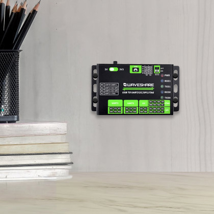
Reserved screw holes
Easy to mount, industrial metal case, rugged & durable
Interface And Mode Description
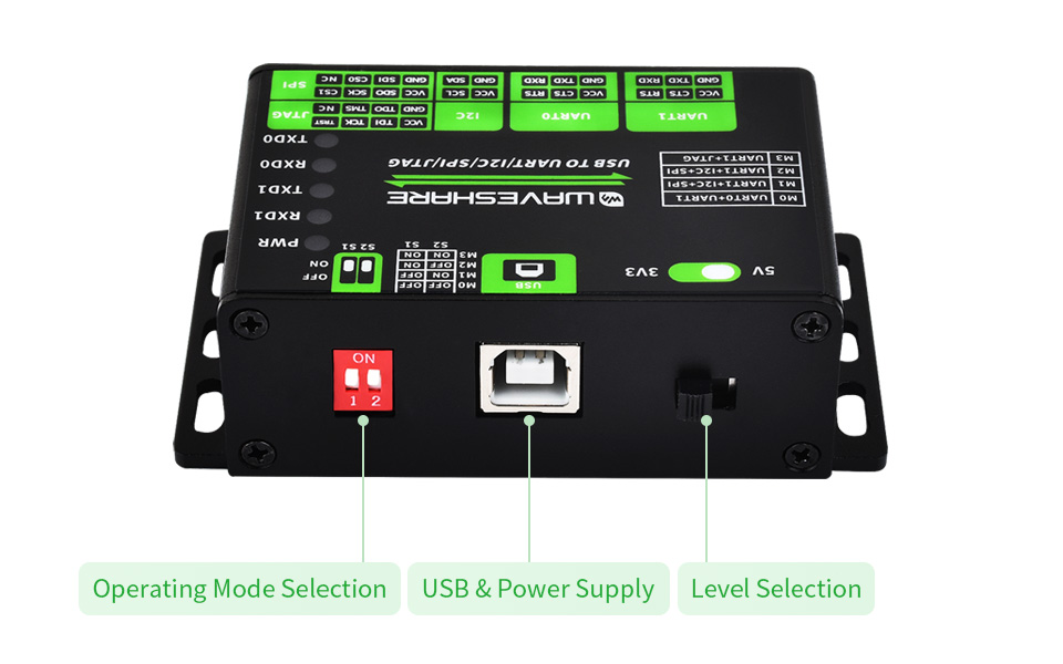
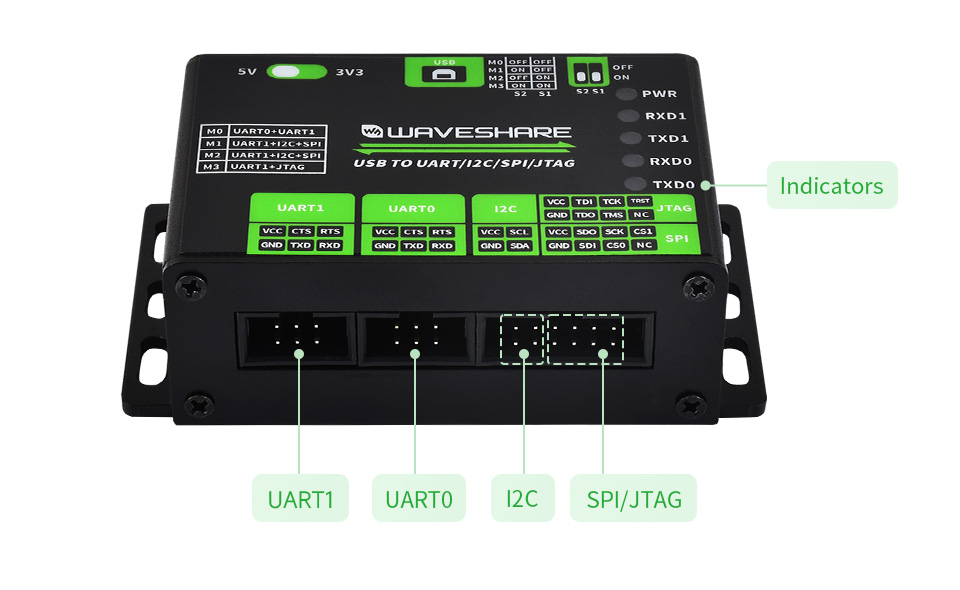
| INDICATOR INTRODUCTION |
| PWR |
power indicator, lights up while the USB is connected and voltage is detected |
| RXD1 |
UART1 receiving indicator, lights up when the device port sends data back |
| TXD1 |
UART1 sending indicator, lights up when the USB port sends data |
| RXD0 |
UART0 receiving indicator, lights up when the device port sends data back |
| TXD0 |
UART0 sending indicator, lights up when the USB port sends data |
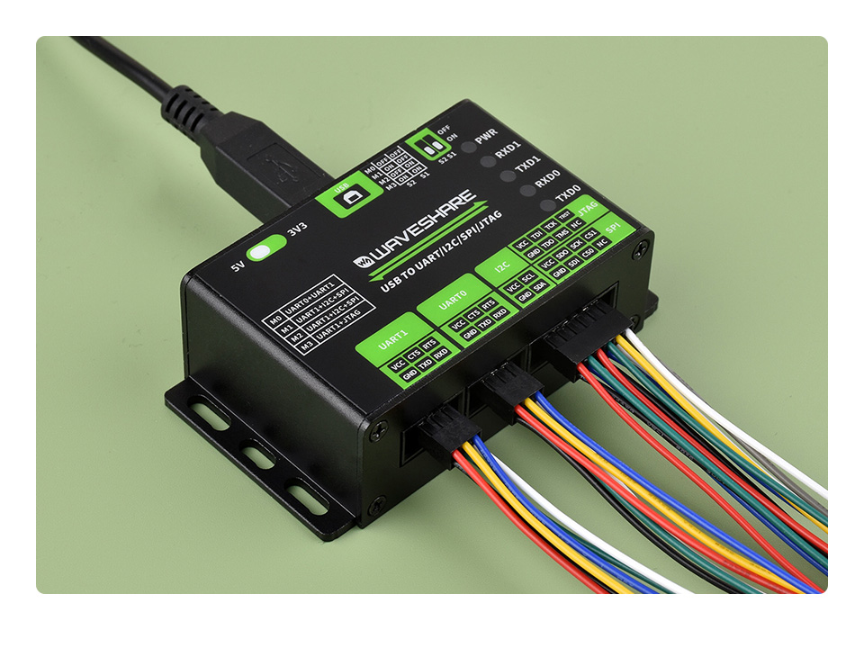
Product Show
Outline Dimensions
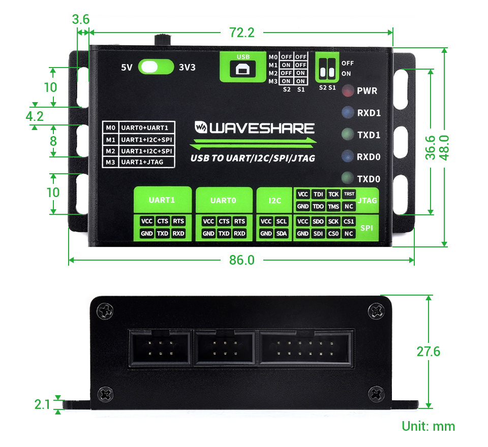
* The above dimensions are measured manually. there is about 1mm error.
Resources & Services

* Resources for different product may vary, please check the wiki page to confirm the actually provided resources.